How To Set Scale In Visio
What's especially nice near Visio is that it can practice much of the measuring and dimensioning work for you. Tools such as the dynamic grid and shape extension lines make it quick to position shapes exactly, and smart dimension line shapes adhere to shapes such as walls and automatically display measurements. In addition, if you start a diagram using ane of Visio'due south built-in templates, bug of drawing scale and measurement are already taken care of. For example, the Part Layout template sets up the diagram and so that 1/2 inch (in.) on the drawing folio represents 1 foot (ft.) in the real globe, a standard architectural drawing scale (see Figure 16-1). You tin print the drawing page on ordinary, letter-sized paper, but when you view it on the screen, the rulers show that it represents an area of 22 ft. by 17 ft. That's the beauty of a drawing scale. Information technology allows you to accurately represent existent-world objects in a manageable size.
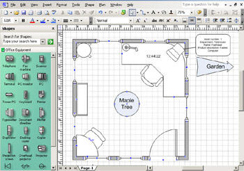
Figure sixteen-i: When y'all draw to scale, Visio displays the real-world size of objects in the rulers.
The sections that follow tell you how to set up a new drawing scale if you're cartoon from scratch or just want to change the scale Visio supplies. Yous tin choose the units of measure you desire to piece of work with as well. Whenever you lot're drawing to scale, the rulers and filigree go important tools for positioning shapes precisely. Later on sections tell you how to customize their settings to suit your working style.
Working with a Cartoon Scale
If you have worked with measured drawings earlier (and yous have if yous've ever used a map), you empathise why a drawing scale is necessary. In an architectural or landscape drawing, you might need to correspond an area of thousands of feet on a manageable sheet of paper; for a map, you might even be cartoon an area of thousands of miles. Conversely, if yous're detailing an intricate item for manufacturing (such as a special screw), the drawing of the object might need to exist many sizes larger than the object itself. Yous tin do this using a drawing scale, which is simply the ratio of the size of the drawn object to the size of the bodily object. For example, floor plans often have a drawing scale of i/3 in. = 1 ft., where ane/3 in. of newspaper is equal to 1 ft. of real-life surface expanse. Similarly, a technical cartoon of a commodities or a machined part might require a cartoon scale of 10:1, where 10 millimeters (mm) on the page represents 1 mm of actual commodities. Visio drawings can use very different drawing scales, as Figure sixteen-2 shows.
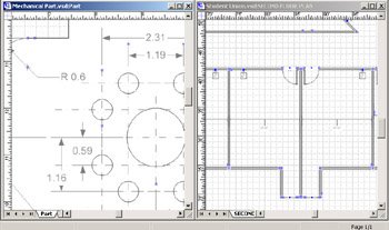
Effigy 16-2: In this mechanical role drawing, 1 in. on the page represents 2 in. in real life, and in the floor plan drawing, 3/sixteen in. on the folio represents 1 ft.
Well-nigh Visio solutions automatically set up the cartoon scale to one that is common for the blazon of drawing. For case, when you lot open a new Space Program drawing, the cartoon calibration defaults to 1/8 in. = 1 ft. Drawings that represent concepts (organization charts, flowcharts, data catamenia diagrams, and so on) rather than real-world objects apply a drawing calibration of 1:one (or no calibration).
You can change a diagram's drawing scale at any time. You tin can even specify a unlike drawing scale for each page, making it easier to provide both detailed and overview information in the same drawing.
Setting a Folio'southward Drawing Calibration
If you're creating a new drawing without using a Visio solution, your but option is to set the cartoon calibration yourself. To avert any unfortunate surprises, information technology'due south best to specify a drawing scale before you begin cartoon.
To specify the cartoon calibration for a page, choose File, Page Setup, and then click the Drawing Scale tab, shown in Figure 16-3. You lot tin can select a predefined scale or specify your own. The predefined scales include common architectural, metric, and engineering scales.
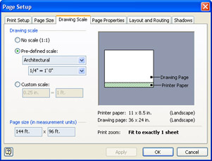
Figure sixteen-3: You can change drawing scale options in the Page Setup dialog box (cull File, Page Setup).
When you specify a cartoon scale, the Page Size fields at the lesser of the Drawing Scale window display how many of the cartoon units volition fit on the page. For example, if you lot prepare a drawing scale of 1 mm = 1 1000 on a letter-sized page (215.9 mm wide by 279.4 mm long), these fields will show that the page can stand for an area that is 215.nine m wide by 279.4 k long.
| Caution | Exist sure to double check your units of measurement to avert foreign results. |
![]()
Inserting a new page
When you lot insert a new page in a diagram, y'all tin can specify a dissimilar drawing scale. If yous don't, the new page inherits the drawing scale of the electric current page. When yous choose Insert, New Page, the Page Setup dialog box appears, which lets you make up one's mind the drawing scale and other settings that might differ from previous pages.
![]()
Displaying the Cartoon Calibration
You create a drawing to communicate, just other people can't empathise your drawing if they don't know what drawing scale you've used. The easiest way to provide this information is to apply the Drawing Scale shape, which is included only with Visio Professional person (meet Figure 16-4). This shape displays the drawing scale you have selected on the diagram.
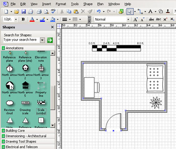
Figure 16-four: Visio Professional includes the Drawing Scale and Calibration Symbol shapes, which automatically display a drawing'due south scale. Visio Standard doesn't include these shapes.
The Drawing Scale and Scale Symbol shapes are in the Annotations stencil. This stencil is automatically opened with many solutions, such as a flooring programme, but if it isn't already available, y'all can open the stencil by choosing File, Shapes, Visio Extras, Annotations. To display either shape on the drawing folio, merely drag the desired shape from the Annotations stencil onto the drawing page.
Yous tin can change the fashion the cartoon scale is displayed to use the near appropriate form for your audience. To specify how the drawing scale is written, right-click the Drawing Scale shape, then choose Architectural, Civil, Mechanical, or Metric. For example, in a drawing scale where 1 mm on the page equals 1 yard in real life, each of the scale styles would look like this:
-
Architectural 1/64 in. = 1 ft.
-
Civil i in. = 25.four m
-
Mechanical 1/k:1
-
Metric one:k
![]()
If you're using metric units in the drawing with Visio Professional, you lot tin can add together the symbol for Syst me Internationale d'Unites (SI). The SI Symbol shape is located on the Title Blocks stencil (choose File, Shapes, Visio Extras, Title Blocks). This symbol appears as solid block messages, but you can display it as hollow letters with the word "metric" below, every bit Figure sixteen-five shows. Right-click the shape, and then choose Hollow "Metric" SI Symbol from the shortcut menu.
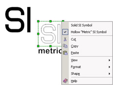
Figure 16-5: The SI Symbol indicates that the drawing uses metric units. To change its advent, right-click the shape, and so choose an option. This shape is bachelor only in Visio Professional.
| Cross-Reference | For details most other title cake shapes and ways to customize them, see "Adding a Title Block to a Diagram," page 134. |
![]()
Using Shapes in Scaled Drawings
Visio shapes are designed to size correctly in scaled drawings. For instance, when you lot drop a chair shape on a page, the chair appears to be the correct size with respect to the other piece of furniture, whether the drawing scale is 1/4 in. to i ft. or 1 ft. to ten ft., as Effigy 16-six shows. In both drawings, the chair is three ft. wide, but it takes up more than space on the screen at the bigger scale (one/4 in. to 1 ft.). What if you driblet that chair onto a page gear up to 1 inch to 1 mile? Will the chair look tiny on the page? As it turns out, Visio ignores the drawing scale in this case, because it doesn't make sense to brandish a chair at real-world size at such a scale. The chair looks the aforementioned as it does when dropped on an unscaled (1:ane) drawing folio.
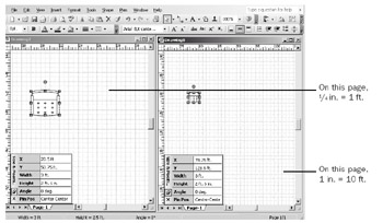
Effigy 16-6: In existent-world terms, a chair is 3 ft. wide regardless of the drawing scale, as the Width box of the Size & Position window indicates. However, the chair'southward apparent size on the page differs according to the calibration, even though both pages are zoomed to 100 pct.
If a shape is designed to be used in a drawing of a particular scale, you lot can still utilize it in a drawing of a unlike scale. Usually yous don't even have to think about whether the shape will work or not—Visio takes intendance of information technology. However, you sometimes come across peculiar behavior if the shape'southward calibration is dramatically dissimilar from the page's calibration, or if the shape wasn't designed with drawing scales in listen. For example, some of the shapes on the Borders And Titles stencil "break" if yous drop them on a page with a very big or very small cartoon scale. "Dramatically different" turns out to be a factor of eight. Visio displays the shape correctly as long as its scale is within eight times the page's calibration, as in the example on the left in Figure 16-vi, where the cartoon scale is 1/4 in. = 1 ft. But in the example on the right, where the drawing scale is i in. to 10 ft., the shape is anti-scaled. That is, Visio ignores the shape's scale and displays it at the size at which it was drawn.
Choosing the Units of Measure for the Drawing
The measurement units you see on the ruler and in the dimensions that Visio reports reflect the real-life size of the objects. For example, if you're drawing a flooring program, you're probably measuring the space in anxiety and inches. The rulers, then, brandish feet and inches, and whatsoever dimensions Visio reports are also measured in feet and inches.
When you use a predefined drawing scale, the measurement unit is automatically set. Architectural and Ceremonious Engineering drawing scales utilize anxiety and inches, Metric drawing scales utilize meters, and Mechanical Technology scales use inches. If you created a custom drawing calibration, the unit of measurement of measure you typed in the drawing scale automatically appears in the Measurement Units field on the Page Properties tab. However, whether you're using default or custom measurement units, you can change the units without changing the cartoon scale. Just as each page tin can accept a different drawing scale, each page can use a dissimilar unit of measurement, as Figure 16-7 shows.
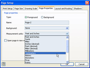
Figure xvi-7: When you insert a folio, you lot tin can specify a unit of measurement of measurement that differs from other pages in the drawing file.
![]()
Spatial and temporal units
Visio offers both spatial (such every bit yards or meters) and temporal (such as weeks or years) measurement options. Yep, temporal units. For example, yous might want 1 in. to equal ane week in a timeline. Hence, past combining the two measurements you can graphically describe the fourth dimension allocated to a projection on a timeline.
![]()
Follow these steps to set measurement units for a page:
-
Choose File, Page Setup, and and then click the Page Properties tab.
-
In the Measurement Units list, select the units you want to use.
-
Click OK.
Tip When y'all utilise the Insert, New Page command to add together pages to a diagram, you can specify unique measurement units for that page on the Page Backdrop tab.
Setting Default Units for the Drawing File
Yous tin specify the default measurement units that Visio uses for the drawing file and so that dialog box options are displayed with the units y'all want. The default units are automatically reflected in all new pages and objects in the cartoon. To exercise this, you gear up the drawing's regional settings by choosing Tools, Options, then clicking the Units tab, equally Figure 16-8 shows. The options nether Default Units let you lot specify the units for the page, text, angles, and duration. Tabular array 16-1 explains each selection.
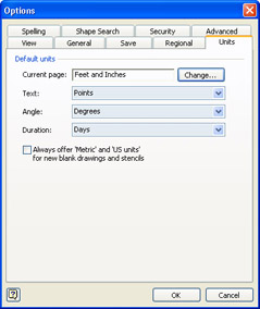
Figure sixteen-8: The default units of measurement that Visio uses for a drawing are a regional setting.
| Option | Clarification |
|---|---|
| Current Folio | Unit of measurement of mensurate for a page'south dimensions, margins, cartoon size, and drawing scale. The units y'all choose determine whether new, blank drawings open with metric or U.S. units. |
| Text | Unit of measure for indents, line spacing, and other text measurements. This unit of measure out doesn't impact type size. The default unit for type size is points (1 point = 1/72 in.). You tin enter type size in another unit of measurement of measure (for example, 1 ft. or 12 in.), only you tin can't change the default. |
| Angle | Unit of measure for the angle of rotation. |
| Duration | Unit of measure for elapsed fourth dimension. |
Customizing the Rulers
When you drag shapes, guides, or guide points on the drawing page, faint lines announced on the rulers that evidence the shape's position so that you tin can move the shape with precision (see Figure xvi-9). Each drawing has both horizontal and vertical rulers, and you can fine-tune your rulers to provide more than or less precision.
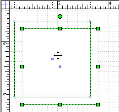
Figure 16-nine: As you elevate a shape, its position is shown on the rulers, which display the units of measure specified with the Page Setup command.
![]()
In any Visio dialog box in which you lot enter a measurement, such as font size or line width, you can employ any unit of mensurate that Visio recognizes. Consider the units that appear in a field to be merely suggestions; you tin type whatsoever unit that Visio supports. For example, you lot can specify a custom width for a line. In the Custom Line Weight box, you tin can type i" or 1 inch or 72 pt. or ii.5 cm and get the aforementioned result. If the field in a dialog box suggests a value—0 in. for paragraph indentation, for example—you can select the field'south contents and blazon a different unit, such as 12 pt.
Visio accepts units of measure in the English language (U.S.) and metric systems, and you can specify angles in radians; decimal degrees or degrees; or degrees, minutes, and seconds. Y'all can also use standard typographical measurements such as picas, points, ciceros, and didots. You tin can spell out the unit names or apply the standard abbreviations.
![]()
The ruler subdivisions are the tick marks that reflect the drawing's units of mensurate and provide a reference for you as y'all position guides or shapes on the page. They also make up one's mind how far an object moves when yous nudge it with an pointer cardinal. The ruler'due south zero betoken shows where the horizontal and vertical rulers both measure out 0 units; information technology is located in the lower left corner of the drawing page unless y'all move information technology.
Ruler subdivisions as well provide points that shapes can snap to. You can set shapes to snap to ruler subdivisions rather than the grid, for example. You lot tin can also determine how easily shapes snap to the ruler subdivision. This kind of snap stickiness is chosen snap strength, and Visio measures it in pixels. The weaker the snap forcefulness, the closer a shape needs to be to a ruler subdivision before information technology snaps to information technology.
Table xvi-two summarizes techniques for customizing rulers in a diagram. The sections that follow explain ruler options in more than detail.
| Chore | Technique |
|---|---|
| Prepare units of measure for rulers | Choose File, Page Setup, and then click the Page Properties tab. In the Measurement Units box, choose the units you want to employ. |
| Set ruler increments | Choose Tools, Ruler & Grid, and so choose Horizontal and Vertical values for Subdivisions. |
| Change the ruler's zero point | Ctrl+drag from the ruler intersection, or Ctrl+drag from a ruler. |
| Return the zero point to its default position | Ctrl+double-click the ruler intersection. |
![]()
Ruler subdivisions and nudge
Ruler subdivisions affect nudge, that nifty play a joke on of using your keyboard'due south arrow keys to move shapes. Each time you nudge a shape using an pointer key, it moves to the next tick mark on the ruler. If you want to nudge a smaller or larger corporeality, you can change the ruler subdivisions (or simply zoom in).
![]()
| Caution | Ensure that NumLock is not enabled on your keyboard when attempting to nudge a shape. If it is, the shape won't nudge. |
Setting Ruler Subdivisions
You tin gear up the ruler subdivisions on the horizontal and vertical rulers separately. To alter the level of detail on a ruler, choose Tools, Ruler & Grid, and then choose one of the following options for the subdivisions:
-
Fine spacing provides the most item, displaying the greatest number of ticks per unit.
-
Coarse displays the smallest number of ticks.
-
Normal falls in between.
The number of subdivisions y'all'll see between units varies depending on the view y'all're using, simply the distance between the subdivisions on the screen remains constant. That is, as you zoom in, you'll encounter more marks betwixt twenty and 30 ft., for example, but the space between each of the marks on the screen is like to the space between the marks at a unlike view, as Effigy xvi-10 shows.
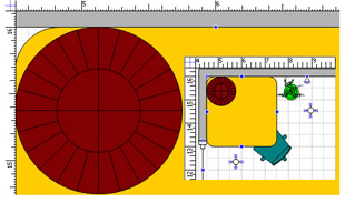
Figure 16-10: For each function layout, the drawing scale is the same and the ruler subdivisions are set to Fine.
Changing the Zero Point
In many measured drawings, it's common to move the zero bespeak. For example, in a flooring plan, you might want the zippo point to marshal with a wall, as Figure 16-11 shows. Y'all tin gear up a separate zero point for each ruler, or you can reset both. For greatest precision, it'southward probably faster to type a value for each zilch point to reset them rather than using the Ctrl+drag technique mentioned in Table 16-ii.
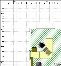
Figure 16-eleven: Concur the Ctrl key, and drag from the ruler intersection to speedily set up the cypher point for both rulers.
To type values for the zero points, choose Tools, Ruler & Grid, and so blazon a value for either the horizontal or vertical Ruler Nothing selection, as Figure sixteen-12 shows. Unlike many page layout applications (such equally Adobe PageMaker or Quark XPress), in which the goose egg point is located in the top left corner, Visio places the default null point in the lower left corner of the drawing folio. By default, the horizontal ruler measures null from the left edge of the page, and the vertical ruler measures nil from the bottom edge of the page.
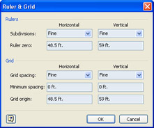
Figure 16-12: For more precision, type exact values in the Ruler Zero boxes to move the zippo point.
| Note | The nothing point specifies the centre of rotation if you rotate your page or a guide on the page. |
If yous change the Ruler Zero value for the horizontal ruler to a positive number (for example, 3 in.), the zippo signal shifts to the right. If you lot alter the value to a negative number (for instance, –three in.), the zero point shifts to the left. Likewise, if you change the value for the vertical ruler to a positive number, the zero point shifts up; if you change information technology to a negative number, the cypher signal shifts downwards. As yous would wait, the ruler measurements are marked with positive and negative numbers on either side of the zero signal.
| Tip | To reset the aught point to its default position, double-click in the upper left corner, where the blue lines cantankerous at the ruler intersection. |
Snapping Shapes to Ruler Subdivisions
When you're aligning shapes in a measured drawing, y'all might observe it more useful to have shapes snap to the increments you've attack the ruler, rather than to the filigree. You tin can also adjust the snap strength setting to suit different magnifications. For example, if you're zoomed in very close and gear up a stiff snap strength, you tin identify shapes more precisely.
To snap shapes to ruler subdivisions, follow these steps:
-
Cull Tools, Snap & Glue.
-
In the Currently Active area, brand certain Snap is selected.
-
Under Snap To, select the Ruler Subdivisions check box.
You might want to articulate the Filigree check box besides.
-
Click the Advanced tab, and then movement the Rulers slider to adjust the snap strength. Alternatively, you can type a value in the Pixels box, rather than use the slider.
-
Click OK.
Cross-Reference For details nigh snapping to other objects, run across "Snapping Shapes for Automated Alignment," page 436.
Controlling Grid Spacing and Origin
Information technology'due south hard to miss the filigree in Visio: it's the set of nonprinting dotted lines on the drawing page that looks similar graph newspaper. You can hide the grid (cull View, Grid), just any diagram you start with a Visio template displays the grid, which is a powerful alignment tool. To accommodate unlike drawing scales and diagram types, the grid is adjustable. You can control the grid'due south spacing and set a stock-still altitude between the lines, and you tin can shift the grid's point of origin. These options are available when you choose Tools, Ruler & Grid.
Grid spacing in Visio varies depending on the magnification, unless you specify otherwise. The term for this is variable filigree, where the grid lines change depending on the zoom level. By contrast, a fixed grid doesn't modify as you lot zoom the view, which is a more useful pick in many measured drawings. In a fixed filigree, grid lines that are 1/4 in. autonomously stay that mode at any magnification.
| Annotation | Because grid settings are part of the properties of a drawing page, y'all tin can take unlike settings for every page in a cartoon. |
Changing Variable Grid Spacing
Even though the grid spacing changes with the zoom level in a variable grid, you can still control how finely spaced the lines are, every bit Figure 16-13 shows. You tin can also choose dissimilar values for the horizontal and vertical filigree lines. To see your options, choose Tools, Ruler & Grid.

Figure 16-thirteen: You tin can change how close together the filigree lines appear. Here, both drawing pages are zoomed to 100 percent, but one grid uses normal spacing and the other fine spacing.
The Grid Spacing values that apply to variable grids are Fine, Normal, and Fibroid. With each, you lot'll meet similar spacing between lines on your screen no matter what view you lot've zoomed in or out to. You can set the Minimum Spacing value to define the minimum value for the space between the lines, at any view. For example, if you choose Fine (which causes grid lines to be closer together) with a minimum space of 1 ft. in a scaled drawing, no thing how far you zoom out, the lines cannot be closer than a foot together.
Setting a Fixed Grid
When you need the grid to prove you stock-still spacing at whatever magnification, specify a stock-still filigree as follows:
-
Choose Tools, Ruler & Filigree.
-
In the Grid Spacing boxes, select Fixed for both Horizontal and Vertical.
-
In the Minimum Spacing boxes, type a measurement for the line spacing.
If you desire an uneven filigree, type different spacing values for Horizontal and Vertical.
-
Click OK.
When you specify Fixed for Grid Spacing, the Minimum Spacing boxes really correspond the maximum value for the distance between filigree lines. That altitude doesn't modify equally you lot change zoom levels, then the infinite your figurer screen displays betwixt grid lines will be different in each view.
Setting the Grid Origin
The grid origin is the point from which the grid is measured. In a variable filigree, you probably don't care about the grid origin, simply in a fixed grid, you might desire the grid lines to start at a specific measurement, which can exist different for the horizontal and vertical lines, as Figure sixteen-14 shows. The grid always originates in relation to the ruler'due south zippo indicate.
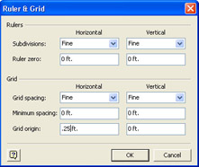
Figure sixteen-14: When y'all enter a positive horizontal value in the Grid Origin box, the grid originates to the right of the naught signal.
By default, the grid origin is at the zero point, which by default is the lower left corner of the drawing page. To change the grid origin, choose Tools, Ruler & Grid, and type a starting measurement in the Grid Origin boxes.
For example, if you type .25 in. for the horizontal grid origin, the first horizontal grid line is fatigued one/4 in. from the ruler's nix point. The remainder of the grid lines are spaced accordingly from that indicate.
How To Set Scale In Visio,
Source: https://flylib.com/books/en/3.433.1.96/1/
Posted by: vizcainocogne1948.blogspot.com


0 Response to "How To Set Scale In Visio"
Post a Comment